Circulator
Stable RF signal routing becomes more challenging when reflected power, port-to-port interaction, and system protection all need to be managed in the same signal path. In many telecom and microwave assemblies, a circulator is used to guide energy from one port to the next in a defined direction, helping engineers control signal flow without introducing unnecessary complexity.
This category focuses on circulators for telecommunication components, with options that span lower VHF and UHF bands through microwave frequency ranges. The available selection is particularly relevant for RF test setups, transmitter chains, antenna interfaces, and high-power signal handling where isolation and insertion loss need to be considered together.
How circulators support RF and telecom system design
A circulator is a passive multi-port device that directs RF energy sequentially from one port to the next. In a typical 3-port design, power entering port 1 is routed to port 2, power entering port 2 is routed to port 3, and power entering port 3 is routed back to port 1. This directional behavior is useful in systems where transmit and receive paths must be managed while limiting unwanted reflections.
In practical telecom environments, circulators are often selected to improve signal isolation between stages, protect sensitive equipment from reflected energy, and support cleaner integration of amplifiers, antennas, and test instruments. They are closely related to devices such as isolators, but circulators provide a more flexible multi-port routing function when the application requires controlled energy transfer between several ports.
Key parameters to evaluate before choosing a circulator
The most important starting point is frequency range. A circulator must be matched to the operating band of the system, whether that is around 135 MHz to 175 MHz, 698 MHz to 960 MHz, 1 GHz to 2 GHz, or well into the microwave region such as 11 GHz to 18 GHz. Choosing outside the intended band can reduce isolation and increase mismatch-related performance issues.
Other core parameters include insertion loss, isolation, VSWR, impedance, and power handling. Lower insertion loss helps preserve signal strength, while stronger isolation improves separation between ports and reduces the impact of reflected or leaked energy. For most RF assemblies in this category, 50 ohm impedance is the expected standard, so compatibility with the rest of the signal chain is usually straightforward.
Connector style and mechanical integration also matter. Many of the listed models use SMA female interfaces, which are common in laboratory, telecom, and microwave applications. If the broader system includes transitions or connector changes, related components such as RF adapters may also be relevant during system layout.
Coverage from standard RF bands to high-power microwave applications
This category includes both general-purpose and high-power models, making it suitable for a wide range of operating conditions. At lower and mid-band frequencies, examples include the Fairview SFC8096 for 800 MHz to 960 MHz and the Fairview SFC1020 for 1 GHz to 2 GHz. These types of devices are useful when compact RF routing and moderate power handling are needed in communication equipment, bench testing, or subsystem integration.
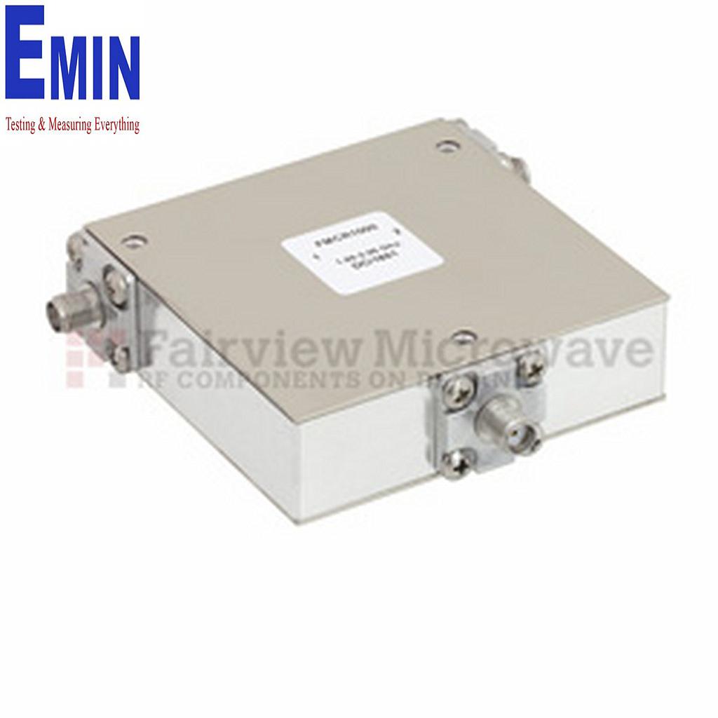
For more demanding environments, high-power options extend the category’s usefulness significantly. Models such as the Fairview SFC3846S cover 380 MHz to 460 MHz at very high power levels, while the Fairview SFC6996S supports 698 MHz to 960 MHz in applications where reflected energy management is especially important. At higher frequencies, parts like the Fairview FMCR1004, FMCR1006, FMCR1008, and FMCR1011 support 2 GHz to 18 GHz ranges with power handling suited to microwave assemblies and specialized RF paths.
Because selection depends heavily on band, power, and allowable loss, many buyers compare circulators alongside other passive signal-management products such as a power divider when designing or upgrading RF distribution networks.
Typical use cases for circulators
One common use case is transmitter protection. When an antenna or connected load is not perfectly matched, some power reflects back toward the source. A circulator can redirect that reflected energy away from the transmitter path, helping preserve amplifier stability and reducing stress on upstream equipment.
Circulators are also used in duplexing and shared-path architectures where multiple functions need to coexist in a compact RF design. In test and measurement environments, they can support more controlled routing between signal sources, loads, and monitoring equipment. Their directional properties also make them useful in microwave bench setups where repeatability and predictable port behavior are important.
In broader telecom component ecosystems, circulators may work alongside switches, couplers, dividers, and matching hardware. Where path selection is required rather than directional passive routing, users may also evaluate telecommunication switches as part of the overall system design.
Examples from Fairviewmicrowave
Fairviewmicrowave is the featured manufacturer in this category, with a range that covers both lower-frequency and microwave circulator requirements. The lineup includes compact models for common RF bands as well as higher-power versions intended for more demanding signal environments.
Examples include the Fairview SFC1317S for 135 MHz to 175 MHz, the Fairview SFC3340S for 330 MHz to 403 MHz, and the Fairview SFC4552S for 450 MHz to 520 MHz. For microwave applications, the FMCR series extends coverage into 2 GHz to 4 GHz, 4 GHz to 8 GHz, 7 GHz to 12.4 GHz, and 11 GHz to 18 GHz. This spread makes the category useful for engineers who need to compare solutions across very different RF bands without leaving the same product group.
Selection tips for procurement and engineering teams
For B2B buyers, the most efficient selection process starts with the operating frequency and maximum forward and reflected power expected in the application. After that, it is worth checking acceptable insertion loss, minimum required isolation, connector compatibility, and the physical constraints of the assembly. These factors typically determine whether a standard model is sufficient or whether a higher-power part is more appropriate.
It is also helpful to think about the circulator as part of the full RF path rather than as an isolated component. Cable losses, connector transitions, nearby passive devices, and mismatch conditions all affect real-world performance. Reviewing the complete signal chain early can reduce redesign time and improve installation consistency across telecom, lab, and industrial RF environments.
Find the right circulator for your RF path
The circulators in this category support a wide range of telecom and microwave design requirements, from moderate-power RF routing to higher-power protection and isolation tasks. With coverage across multiple bands and application types, they provide a practical starting point for engineers, integrators, and purchasing teams working on communication systems, RF test setups, and microwave assemblies.
If you are narrowing down options, focus on band coverage, isolation, insertion loss, connector type, and power rating in the context of the complete system. A well-matched circulator can improve signal handling, reduce reflected-power issues, and make the overall RF architecture more robust and easier to maintain.
-
-
-
-
-
-
-
-
-
-
-
-
-
-
-
-
-
-
-
-
-
-
-
-