Voltage/Current divider
Accurate ratio measurement often depends on components that are easy to overlook. In laboratories, calibration benches, and precision electrical test setups, a well-designed Voltage/Current divider helps scale signals to a usable level while preserving stability, linearity, and repeatability. That matters when the goal is not simply to reduce voltage or distribute current, but to do so in a controlled and measurable way.
This category focuses on precision divider solutions used in electrical and electronic measurement work. Compared with a simple resistor network assembled for basic circuits, dedicated divider instruments are built for higher consistency, lower error, and better long-term behavior in demanding applications such as calibration, reference comparison, and sensitive bench testing.
Why precision dividers are important in measurement systems
A divider is used to produce a known fraction of an input signal. In practice, that simple function becomes much more demanding when engineers need confidence in ratio accuracy across time, temperature change, and different load conditions. This is why precision divider assemblies are commonly selected for metrology, instrument verification, and high-accuracy test environments.
In many setups, the divider works alongside other measuring instruments such as a multimeter or a reference source. If the divider itself introduces ratio drift, loading error, or nonlinearity, the entire measurement chain is affected. A stable divider therefore supports both reliable readings and more meaningful calibration results.
Common error sources in voltage and current divider applications
One of the most frequent issues is resistor tolerance. Even when nominal values look correct on paper, the actual ratio can shift if the resistance elements are not matched tightly enough. In precision applications, small deviations accumulate and become visible in final measurement uncertainty.
Temperature effects are another major factor. Resistance values change with temperature, so a divider used in a warm enclosure or under continuous operation may no longer maintain the same ratio as it did under reference conditions. For high-accuracy work, thermal behavior is often just as important as nominal resistance value.
Loading effect also needs attention. When the connected instrument does not have sufficiently high input impedance, it changes the divider output and alters the intended ratio. For AC and higher-frequency conditions, parasitic capacitance and inductance can further affect performance, making the real response different from the ideal DC calculation.
How to choose the right divider for your application
Selection should begin with the measurement objective. Some applications need a divider for routine bench work, while others require a calibration-grade instrument for comparison against standards. Important considerations include ratio resolution, linearity, input resistance, voltage handling, and the level of stability required over time.
It is also useful to think about the wider test environment. If the divider will be part of a semiconductor or source-measure workflow, related solutions in SMU semiconductor testing may provide additional context for system design. For basic verification or troubleshooting, pairing the divider with the right instrument class can be as important as the divider specification itself.
Another practical point is whether the unit is intended for general-purpose use, decade adjustment, or Kelvin-Varley ratio work. These formats serve different needs. Decade and Kelvin-Varley designs are especially relevant when fine ratio setting, excellent linearity, and repeatable adjustment are required.
Representative solutions in this category
IET LABS is the main featured manufacturer in this range, with products well aligned to precision electrical measurement and metrology-style applications. Rather than covering every possible divider style, the catalog emphasizes instruments where ratio accuracy and long-term stability are central to the design.
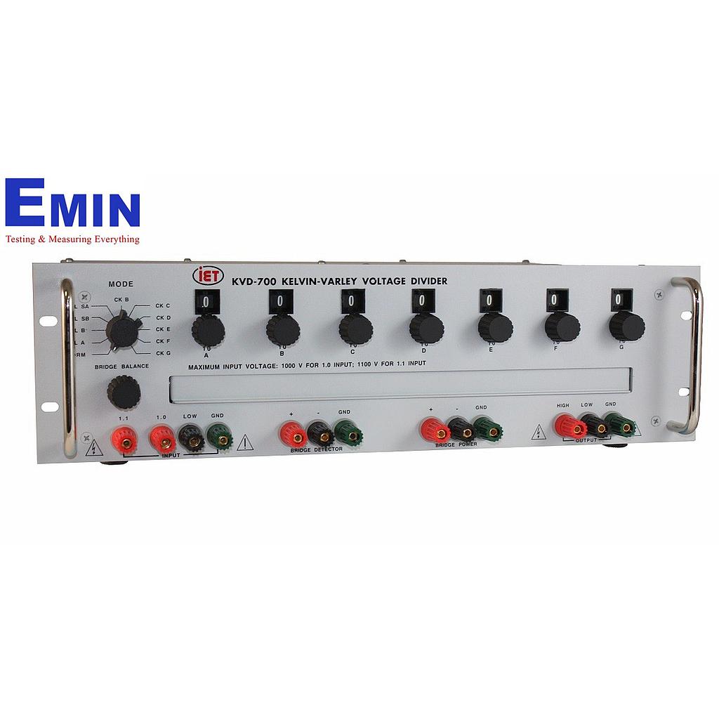
The IETLAB RV722 Kelvin-Varley Voltage Divider is positioned for high-accuracy calibration work, with a structure suited to demanding reference applications. The IETLAB KVD-700 Precision Kelvin-Varley Voltage Divider extends that approach with very fine resolution and tight linearity behavior, making it relevant where small ratio adjustments must remain trustworthy over time.
For users looking at practical ratio-setting hardware, the IETLAB KVD-500 Kelvin-Varley Voltage Divider and the IETLAB 1455 Series Decade Voltage Divider illustrate two common approaches. The 1455 Series is especially useful for engineers who need a decade-style divider with defined impedance and good linearity, while the IETLAB DP 1211 & DP 1311 Voltage Dividers fit applications that require robust, precision resistor-based division in standard model configurations.
Where these dividers are typically used
Precision dividers are commonly found in calibration laboratories, instrument service departments, R&D benches, and advanced electrical test setups. They are useful when a known voltage ratio must be established before comparison with a meter, recorder, bridge, or reference detector. In those cases, the divider is not just an accessory; it is part of the accuracy budget.
They may also support troubleshooting and verification workflows in broader electrical measurement environments. For example, engineers checking protective systems or grounding behavior may use different specialized tools such as an earth resistance/resistivity tester, while dividers remain essential where precision voltage scaling or ratio transfer is the real requirement.
Good practice for stable results
Using a high-quality divider is only part of the solution. To maintain reliable performance, users should match the divider correctly to the input impedance of the receiving instrument, operate within the intended electrical range, and allow adequate thermal stabilization before critical measurements. These steps help reduce avoidable ratio errors.
Periodic calibration is also important, particularly in laboratories and quality-controlled production environments. Some precision divider designs include features that support verification or self-checking behavior, which can simplify maintenance of traceable performance. Even so, routine comparison against known references remains good practice when measurement confidence is critical.
Clean connections, stable ambient conditions, and careful handling also matter more than many users expect. In high-precision work, contact quality, switch condition, and small thermal gradients can influence the final result. A divider should therefore be selected and used as part of a complete measurement method, not as an isolated component.
Finding the right fit for your measurement workflow
This category is most relevant for buyers who need more than a basic signal reduction circuit. If your work involves calibration, ratio comparison, precision voltage scaling, or sensitive electronic measurement, a dedicated divider can improve both consistency and confidence in the data. The available IET LABS models cover several established formats, from decade voltage dividers to Kelvin-Varley designs used in more exacting applications.
When comparing options, focus on the conditions of use, the required ratio accuracy, and how the divider will interact with the rest of the test chain. A well-matched instrument helps reduce uncertainty at the source and supports better decisions throughout the measurement process.
-
-
-
-
-
-
-
-
-
-
-
-
-
-
-
-
-
-
-
-
-
-
-
-